 |
Maxwell's Reciprocal Diagrams | Maxwell Legacy Concepts |
|---|
In a nutshell |
Maxwell had a continuing interest in mechanics, partly because the ethos of mid-19th century natural philosophy was to look for mechanical explanations but also because of his curiosity about mechanical systems. At King's College, London, he taught engineering students and this could well have been the motivation for looking in more detail at the forces involved in frameworks of joists, beams, girders and so on that form part of the structure of roofs, bridges, cranes and mechanical supports of all kinds. At King's College, London, he taught his students how to find the forces in such structures and in 1864 he wrote the first of 2 papers On reciprocal figures and diagrams of forces. His second paper in 1870 took the subject a lot further and earned him the Keith Prize of the Royal Society of Edinburgh. The general idea behind framework structures is to imagine that the joints between individual elements or bars are free to rotate. If a framework deforms or collapses when in place with its intended load then it has too few elements; if it has just enough members to be stiff it will support the load, with each element in tension or compression. The forces can then be calculated; if it has too many bars it is described as 'over-determined' and the elastic properties of each element need to be known before any attempt can be made to see what the stresses and strains might be. The usefulness of jointed frameworks all goes back to the properties of real-world building materials. Wooden beams and metal girders will break much more readily if bent than if stretched or compressed. Structural designs that minimise bending torques will be intrinsically stronger. Of course in practice roof trusses are nailed or pinned together, girders are rivetted or welded, etc. but the underlying strength of a well-determined construction does not rely on the ability of the joints to resist twisting but on the ability of the members to take tension ('ties') or compression ('struts'). It is this kind of framework that Maxwell developed his reciprocal diagram techniques for. Maxwell's reciprocal diagram for a given structure is essentially a superposition of polygons, each representing the forces applied at the joints of the structure. When drawn to scale, the polygons represent both the directions and magnitude of the forces. Given the proposed shape of the structure and its loading, what is the force in each member? Nowadays such a problem is solved by computer but even today not everyone can program a computer or even afford the bespoke software that produces the answer. Maxwell taught his students how to solve the problem 'graphically'. All that was needed was a clean sheet of paper, a pencil, parallel ruler and scale, and a flat board to draw on. Every student in the class could find the answer. This wasn't an exercise just for students. Engineerss have said that Maxwell's method had a major impact on the field of structural engineering. The diagram to the right from a 1915 textbook on applied mechanics shows a loaded framework and below it the reciprocal figure of the forces, with the method credited to Clerk Maxwell. It is very similar to one of many diagrams included by Fleeming Jenkin, first Professor of Engineering at Edinburgh University, in his article on Bridges in the 9th edition of the Encyclopaedia Britannica, published in 1876.
|
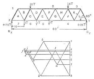 The top figure shows a classic 'Warren girder', asymmetrically loaded with 2 tonnes and 5 tonnes (e.g. a van and a small lorry on a bridge). The lower diagram is the reciprocal figure of the forces. The top figure shows a classic 'Warren girder', asymmetrically loaded with 2 tonnes and 5 tonnes (e.g. a van and a small lorry on a bridge). The lower diagram is the reciprocal figure of the forces. |
|---|
| Technical detail | Maxwell was not the first to draw polygons of force, as he readily acknowledged. He credits the almost contemporary work of Macquorn Rankine as leading in the same direction he was going but developing the reciprocal figure concept mathematically was Maxwell's own idea that enabled him to introduce several embedded concepts. Maxwell's first paper is mainly about plain frameworks. He points out that for determined structures, if there are j joints there will be (2j - 3) bars. This condition is necessary but not sufficient. Since every line in one figure has only two ends, every line in the other figure must also belong to two and only two closed polygons. Later in his paper, he extends the reciprocal diagram concept to three dimensions, pointing out that the reciprocal figure will be possible only if the number of bars is (3j-5). He closes his first paper pointing out that in 3 dimensions the sides of a face may not be in the same plane and Hence the mechanical interest of reciprocal figures in space rapidly diminishes with their complexity. The practical advantage of a framework that has just the right number of members to be stiff is considerable. If one piece is made too long or too short then the framework adjusts its shape (slightly) but develops no internal strain apart from that caused by the load. If the structure has one or more redundant members, then there will be internal strain over and above that provided by the load. A member made too short or too long will exacerbate the internal strain and since excessive strain leads to failure then the aim of both designer and constructor is to build frameworks with a minimum of internal strain before being loaded. The forces within a framework with one or more redundant members can't be solved from just the equations of statics. In a supplementary paper to the Philosophical Magazine in 1864, Maxwell showed how to solve apparently over-determined structures by including the elasticity of the members. If each member in a framework can be extended or compressed, the extra freedom allows the forces and the accompany length changes to be calculated, assuming the elastic properies of the members are known. Maxwell's second paper published by the Royal Society of Edinburgh On reciprocal figures, frames and diagrams of forces is a Maxwell classic: over 50 pages (in his Collected Papers) that start out in the clear open landscape of the readily intelligible before taking the subject into the depths of theoretical development. Notwithstanding his downplaying the usefulness of reciprocal figures in three dimensions in his earlier paper, he extends his concepts so that they can be applied not just to frameworks but to continuous media. Edward John Routh was Maxwell's contemporary at Cambridge who deprived him of the Senior Wrangler honour. In 1891 Routh published his definitive two-volume Treatise on Analytical Statics that devoted a chapter to graphical methods. Fleeming Jenkin was an early adopter of Maxwell's reciprocal diagrams. He promoted them in an article in the Transactions of the Royal Society of Edinburgh in 1869 in which he demonstrated how they could be used for girders, roofs and bridges. The figure on the right is an illustration taken from this article. The top diagram shows a roof framework. The reciprocal diagram is shown below. Jenkin comments that Maxwell's method was 'a remarkably simple and accurate method of calculating the stresses in framework. ... When compared with algebraic methods, the simplicity and rapidity of executation of the graphic method is very striking'. Nowadays, for anyone with access to a suitable computer application, the pendulum has swung the other way. JSR 2016 |
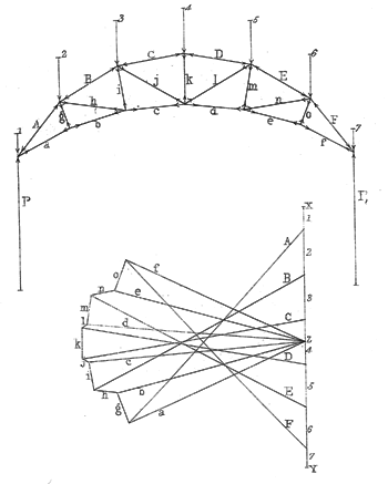 Fleeming Jenkin's sketch for a uniormly loaded roof frame with ties(top), with the corresponding reciprocal force diagram below. Fleeming Jenkin's sketch for a uniormly loaded roof frame with ties(top), with the corresponding reciprocal force diagram below. |
|---|